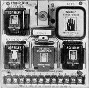
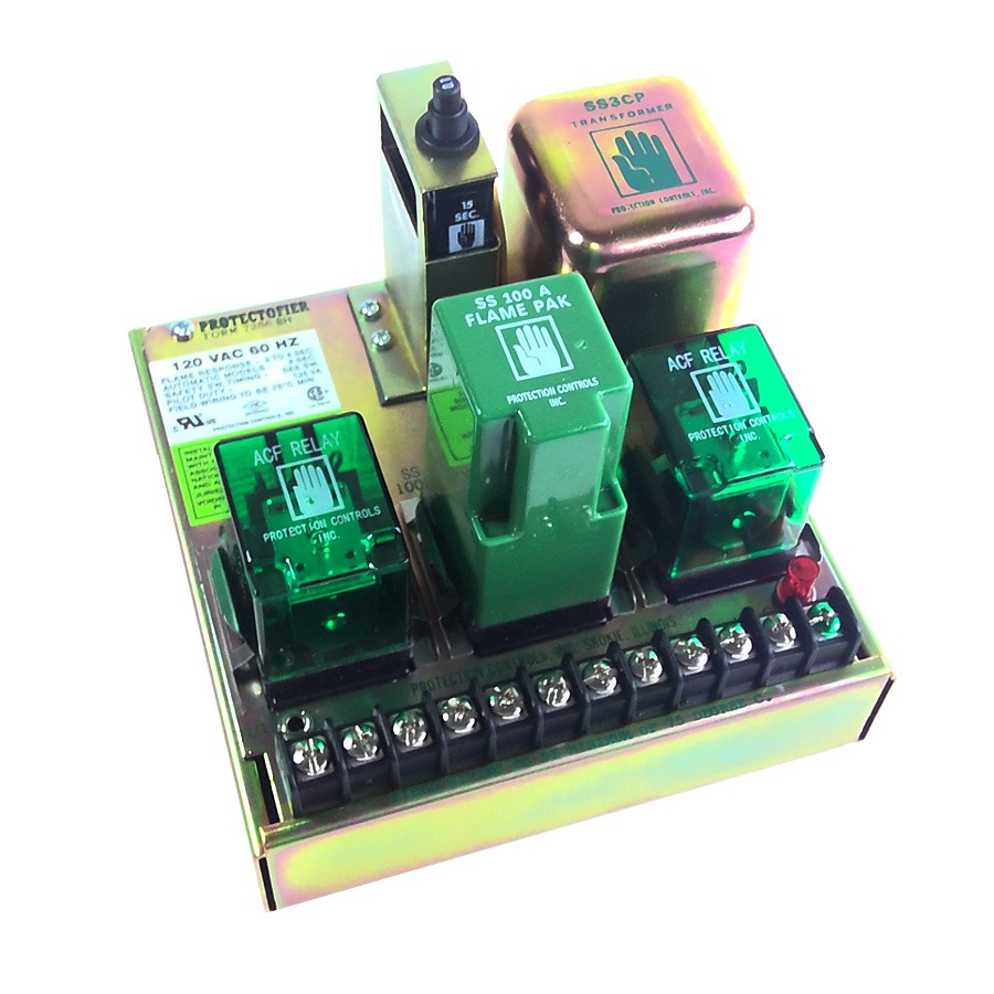
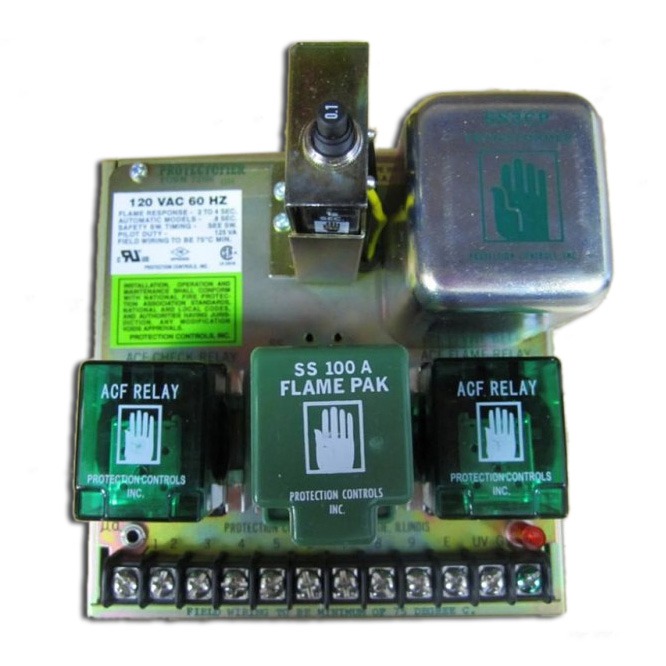
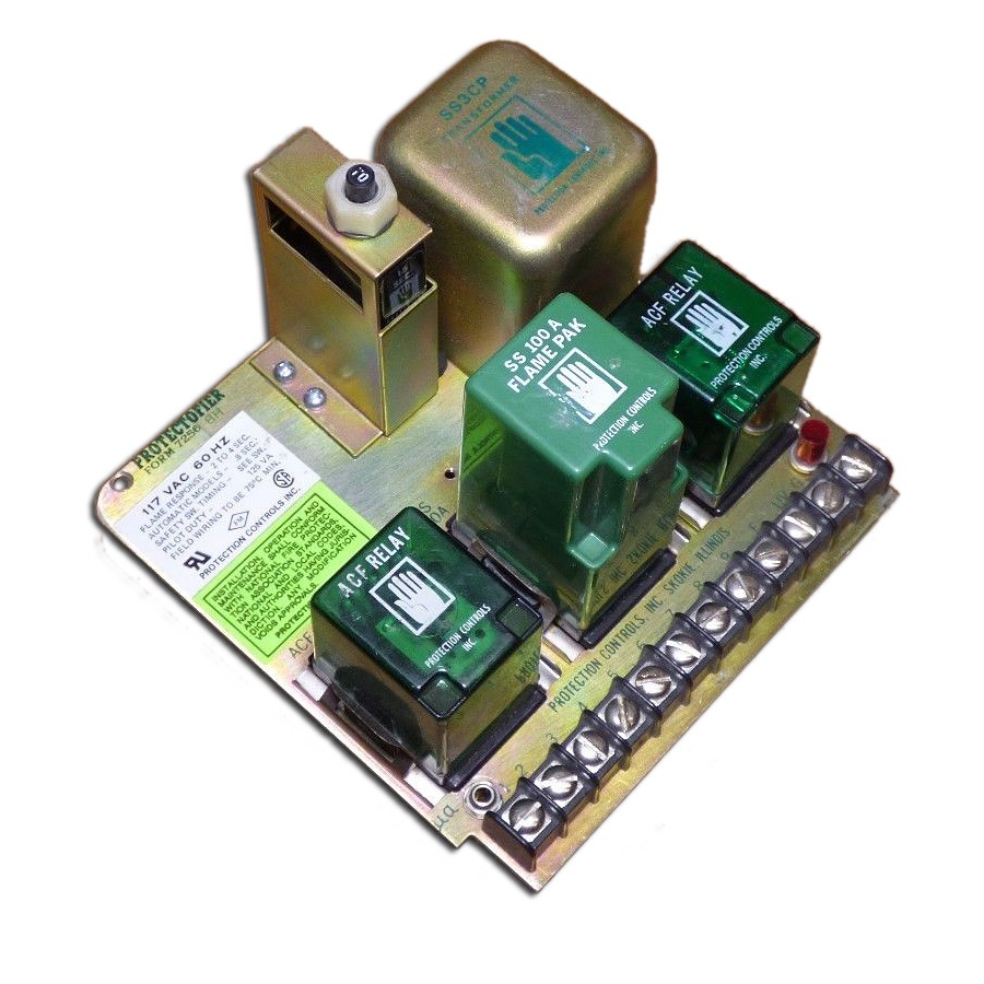
Protection Controls Protectofier 7256 Bulletin. The timofier provides purge time and ignition trial time.
Protection Controls Products 7256 Protectofiers
I ngl ebu r protectofier form7256-ah note.
Protectofier wiring diagram. 10 minutes for manual model only to purge the time. Letter suffix h in form number indicates protectofier provided with contact for flame failure alarm shownstandard trial for ignition period is. Protectofier 6642V Combustion Safeguard Bulletin.
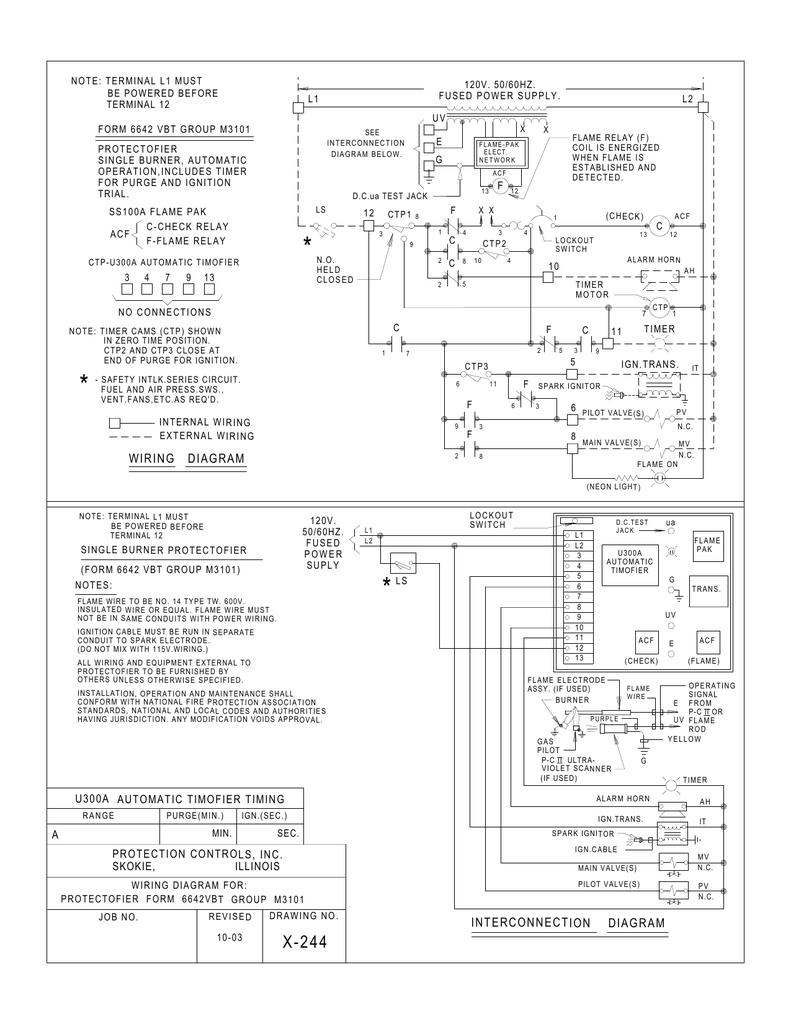
Protectofier 7256 Combustion Safeguard Bulletin. All wiring and equipment external to protectofier to be furnished by others unless otherwise specified. Fused power supply protectofier single burnerautomanual operationincludes ignition tr ial mer.
Complete shutdown and restart should be made. MUST BE NEON POC 6 PR OF CLOSURE SW. The ignition trial time is deducted from the motor time cycle 12 1 1-14 2 3 4 and 6 minutes available for manual and automatic models.
Man-2006 Last modified 1272017 Contains updates included in Firmware v12x2 2016 The Protectowire Co Inc. P ROT EC FI M 7256-BH X-341 REVISED 6-04 120V. 60 Washington Street Pembroke MA 02359.
Open type control shown. Wiring Designation and Terminal Number Comments R177A a RA890F RM7890A1015 power12 limit1-5 motor3 ignition4 controllerRWB detectorFG Remove Series 10 Controller and rewire. Interconnection diagram wiring diagram c 1 7 f 1 4 c.
Position the passenger side photo-eye assembly 96 from the inside edge of the inside conveyor guide rail to the front of the base stand as shown in Picture 6. Protectofier form 664zvblnr group m3 102 job no. All wiringand equipmentexternalto protectofier to be furnishedby othersunlessotherwisespecified.
The ignition trial time is deducted from the motor time cycle12 1 1-14 2 3 4 and 6 minutes available for manual and automatic models. Protection Controls Protectofier 6642 link Download this PDF for more information. Interconnection diagram wiring diagram c 1 7 f 1 4 c.
P rot ec fi m 7256-bh x-341 revised 6-04 120v. Terminal l1 must be powered before terminal 12 no connections 13 12 6 8 9 10 11 3 6 3 9 note. Standard ignition trial time is 15 seconds.
Wiring diagram and sequence of operation are available upon request. FUSED POWER SUPPLY PROTECTOFIER SINGLE BURNERAUTOMANUAL OPERATIONINCLUDES IGNITION TR IAL MER. PROTECTOFIER FORM 6642VT GROUP MP3101 X-379 REVISED 1-05 PURGE GN.
Connections to PROTECTOFIER must be made at terminals in accordance with wiring diagram furnished for a specific application. Nationaland local codesand authoritieshaving jurisdictionany modificationvoidsapproval. The emitter has only two wires and position it on the mechanical room side of the wash bay the RECEIVER photo-eye requires more field wiring than the emitter.
10 minutes for manual model only to purge the timeStandard ignition trial time is 15 seconds. P-C II Ultra-Violet Sensor Bulletin. Protection Controls Protectofier 7256 link Download this PDF for more information.
Terminal l1 must be powered before terminal 12 single burner protectofier form 6642 vb group m2101 revised 3-03 ls l2 7-pbfor manual operation. How to wire the oil furnace cad cell relay - YouTube. Protectofier 6642FF Combustion Safeguard Bulletin.
Interconnection diagram if used e uv g wiring diagram c 1 7 f 1 4 f 2 5 f 2 8 flame on note. Protectofier 7256AH Manual Protectofier 6642BH Auto Service Manual for Protectofier. All wiring and equipment external to protectofier to be furnished by others unless otherwise specified.
Diagram e uv g ls 1 2 3 4 5 6 7 8 9 e uv g single burner protectofier form 7256bnrh l1 l2 120v. Same as RA890F except does not have proof of flame terminal terminal 5 on RA890EF. Protectal Unified Control Panels Bulletin.
Letter suffix e after form number indicates enclosed model. Add jumpers as indicated. 5 POC PROOF OF CLOSURE CONTACTS FROM MAIN VALVES DistributedubyuRelevantuSolutionsuu18888583647uurelevantsolutionscom.
Protectofier 6642VA Manual Protectofier 6642VB Auto Protectofier 6642VT POC Service Manual for Protectofier. Protectofier form 7256-ah x-340 revised 6-04 form 7256ah protectofier si ngl ebu r manual operation acf c- h ekr lay f-flame relay wiring di agr m ls all wiring and equipment external to protectofier to be furnished by others unless otherwise specified. Installation operation and maintenance shall conform with national fire protection association standards national and local codes and authorities having jurisdictionany modification voids approval.
Requires Q270A Subbase with RA890F. FORM 7256BH Distributed5by5Relevant5Solutions55Q888Q858Q364755relevantsolutionsQcom. Fused power supply open type control shown.
The timofier provides purge time and ignition trial time. Form 7761 Non-Adjustable Purge Timer Wiring Diagram. CAUTION Recommended operating temperatures and volt- age must be followed.
Installation operation and maintenance shall conform with national fire protection association standards national and local codes and authorities having jurisdictionany modification voids approval.
Protection Control Protectofier 7256 Flame Safeguard
Protection Control Protectofier 7256 Flame Safeguard

Addressable Fire Alarm System Wiring Diagram Download Wiring Diagram Fire Alarm System Alarm System

Wiring Diagram Of Motorcycle Honda Xrm 125 Http Bookingritzcarlton Info Wiring Diagram Of Motorcycle Honda Xr Diagram Template Wiring Diagram Engine Diagram

Diagram Of Spitronics Pluto M20 In 2021 Wiring Diagram Diagram Wire

Dolphin Gauges Wiring Diagram Best Of Wiring Diagram Diagram Solar Energy Diy

16 Motorcycle Remote Start Wiring Diagram Motorcycle Diagram Wiringg Net Circuit Diagram Wiring Diagram Motorcycle Wiring
Interconnection Diagram Wiring Diagram
Protection Controls Products 6642 Protectofiers

Interconnection Diagram Wiring Diagram
Protection Control Protectofier 7256 Flame Safeguard

Kobelco Sk200 Wiring Diagrams Diagram Wire Repair Manuals
Interconnection Diagram Wiring Diagram

Peugeot Wiring Diagram 206 Wiring Diagrams All Peugeot Wiring Diagram Engine Diagram

On Free Wiring Diagrams Wiring Diagram Electrical Motorcycle Wiring Motorcycle Wiring Diagram
Protection Control Protectofier 7256 Flame Safeguard

Fire Alarm Wiring Diagram Pdf Wiring Diagram And Schematic Diagram Images Fire Alarm System Alarm System Fire Alarm

Protection Control Protectofier 7256 Flame Safeguard

Home Theater Speaker Wiring Diagram Wiring Diagram Access Control System Security Camera Wiring Diagram